Thermography Test in Solar PV Plant
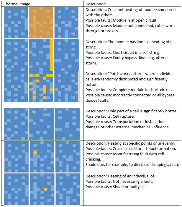
Even a small technical defect is sufficient to have considerable negative effect on the solar yield – and therefore the economic viability of a photovoltaic plant. The use of thermography secures the value of the PV plant in the long run determining the causes of error quickly and reliably, and to eliminate them. At the forefront of a thermographic analysis is the identification of hotspots, which not only cause yield losses, but also represent areas of danger. This also plays an important role when it comes to the issue of warranty claims. Imager tests are furthermore carried out on electrical components.
The benefits of undertaking Thermography tests are as below: –
- Early identification of faults,
- Avoidance of yield loss
- Increasing operational safety, prevention of fire danger
- Fast and safe inspections
- Identification of hotspots, modules at open circuit, short circuits, delamination, cell rupture, corroded and loose contacts, overheated connection sockets
- Creation of added value for solar engineers and plant operators
The most common observation under thermography is hotspot; there are generally two consequences of hotspots: –
- The electricity yield decreases, as individual cells or the entire module are consuming electricity instead of generating it.
- Unwanted electricity consumption heats up the cells and modules. Aside from the damage to individual cells and a further reduction in the electricity yield, this can also lead to a real fire risk.
Besides individual cells and modules, electrical components can also be checked using thermography. Corrosion on electrical conductors and connectors or loose cables can lead to electrical transfer resistances, indicated by a considerable rise in temperature. This means that, in addition to the generating modules, electrical components can also be checked.
Tips and tricks on measurements and avoiding errors
- Meteorological prerequisite: Testing should take place on clear, dry days, with intensive solar radiation (approx. 600 W/m²). It is recommended to carry out the measurement when outdoor temperatures are low (e.g. Morning or evening).
- Correct alignment: The energy radiated is dependent on direction, i.e. during the IR temperature measurement, the alignment of the imager in relation to the module surface should be 60 – 90 °. The PV module should be aligned so that it is as vertical as possible to the direction of solar radiation.
- Interpretation & Evaluation: If temperature deviations occur during the evaluation of the thermograms, this does not necessarily mean that the affected modules must be faulty. Proper interpretation & evaluation is necessary.
- Hotspots do not necessarily indicate a defective cell: Not every hotspot automatically indicates a fault in a solar cell. Modules with significant deviations are not necessarily faulty, they may just be dirty and should be cleaned.
References: